

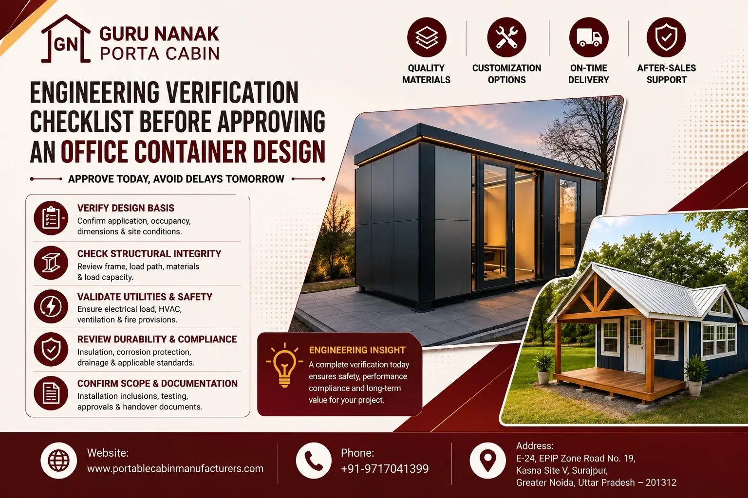
Engineering Verification Checklist Before Approving an Office Container Design
25 Jul, 2026
An office container drawing should not be approved merely because its dimensions, room arrangement and external appearance look acceptable. Design approval is an engineering gate that determines whether the finished unit will safely accommodate its occupants, equipment, utilities, transportation loads and installation conditions.
A technically complete review connects the intended application with structural load transfer, material specifications, openings, insulation, electrical demand, ventilation, lifting points, support conditions and inspection requirements. Missing any of these inputs can result in late modifications, unclear supplier quotations, installation delays or performance problems after commissioning.
Guru Nanak Porta Cabin approaches customized office container planning through project-specific inputs rather than size alone. For engineers and procurement teams, however, the final approval must remain tied to documented requirements, approved drawings and measurable acceptance criteria.
Before approving an office container design, verify
- Intended application and occupancy
- External and clear internal dimensions
- Structural design basis and load path
- Material grades, sections and thicknesses
- Reinforcement around doors, windows and service openings
- Floor and roof loading requirements
- Insulation type, thickness and continuity
- Electrical connected load and distribution
- HVAC, ventilation and condensate provisions
- Fire, emergency and occupant-safety requirements
- Roof drainage and water-ingress protection
- Corrosion-protection system
- Lifting points and transport dimensions
- Support, foundation and anchoring requirements
- Manufacturing tolerances
- Inspection and testing requirements
- Installation inclusions and exclusions
- Handover documents and approval responsibilities
Manufacturing should begin only after unresolved technical comments have been closed or formally accepted by the responsible parties.
1. Why Office Container Design Approval Requires Engineering Control
The general-arrangement drawing is only one part of office container design approval. It shows the visible configuration, but it may not establish whether the structure, utilities and materials are suitable for the actual site.
Two office containers with identical external dimensions can perform differently because of differences in:
- Structural-member sizes and steel thicknesses
- Number and location of openings
- Floor construction
- Roof slope and drainage
- Insulation material and installation quality
- Electrical connected load
- Air-conditioning requirements
- Coating system
- Lifting arrangement
- Support-point configuration
- Site wind, humidity, temperature and corrosion exposure
The approving engineer should therefore treat the drawing as the output of a defined design basis—not as the design basis itself.
Engineering answer block
An office container design is ready for approval only when its layout, structure, materials, utilities, transportation method, support conditions and acceptance criteria are coordinated and documented.
2. Establish the Engineering Design Basis
The design basis converts operational requirements into technical inputs. Without it, manufacturers may interpret the same RFQ differently, making quotation and design comparisons unreliable.
Engineering Design-Input Checklist
| Design input | Information required before approval | Why it matters |
|---|---|---|
| Application | Site office, QA/QC office, meeting room, documentation room or another defined use | Establishes occupancy, layout and equipment needs |
| Occupancy | Normal and maximum number of users | Influences space, ventilation, lighting and electrical demand |
| Site location | Project address and environmental exposure | Supports climate, access and corrosion review |
| Operating period | Temporary, semi-permanent or extended use | Influences material and maintenance decisions |
| External dimensions | Length, width and overall transport height | Affects capacity, access and transportation |
| Internal dimensions | Usable area and clear height | Determines actual occupancy and equipment space |
| Furniture and equipment | Desks, cabinets, printers, displays and technical equipment | Affects layout, floor load and electrical demand |
| Openings | Doors, windows, exhausts, cable penetrations and AC openings | Requires coordination and local reinforcement |
| Utilities | Incoming power, water, drainage and communications | Determines interface points |
| Environment | Heat, monsoon, dust, humidity, pollution, wind or coastal exposure | Influences envelope and protective systems |
| Relocation | Expected frequency and handling method | Affects lifting, inspection and connection details |
| Foundation | Blocks, pedestals, slab, steel supports or other system | Controls load transfer and levelling |
| Project requirements | Client specifications, inspection stages and documentation | Establishes contractual acceptance criteria |
| Delivery route | Road width, height restrictions, turning radius and site entry | Determines transport feasibility |
| Installation access | Crane position, reach, capacity and working clearance | Determines unloading feasibility |
Space-per-Person Example
A preliminary occupancy check can be expressed as:
Space per person= Usable floor area/Number of occupants
If a container provides 24 m² of usable floor area for eight regular occupants
24÷8=3 m2 per person
This figure is only an early planning indicator. Furniture layout, circulation, storage, emergency movement, ventilation and applicable workplace requirements must also be reviewed.
3. Verify the Structural System and Load Path
A containerized office requires a continuous and understandable load path.
Typical load path:
Roof and imposed loads
↓
Roof members and perimeter frame
↓
Corner posts and wall framing
↓
Base frame and floor members
↓
Defined support points
↓
Foundation or prepared ground
The structural review should address both in-service conditions and temporary conditions created during lifting and transportation.
Structural Verification Checklist
| Component | Verification requirement | Warning signs |
|---|---|---|
| Roof frame | Member arrangement, drainage slope and applicable loads | Excessive spans, ponding risk or unclear load basis |
| Wall frame | Vertical and lateral-load transfer | Discontinuous framing or unsupported panels |
| Corner posts | Load transfer during service and lifting | Modified or weakened corner zones |
| Base frame | Support spacing and floor-load distribution | Supports not aligned with load-bearing members |
| Floor members | Distributed and concentrated loads | Undefined equipment loads or visible flexibility |
| Openings | Framing and local reinforcement | Cut-outs introduced without structural review |
| Connections | Welds, fasteners and continuity | Intermittent or undocumented critical connections |
| Lifting points | Location, identification and handling method | Lifting from unapproved members |
| Anchoring | Requirement based on exposure and installation | Assumption that self-weight is always sufficient |
| Modular joints | Alignment, sealing and load interaction | Site-made connections without approved details |
Why Door and Window Openings Matter
An opening interrupts the original load path. Its effect depends on its size, position and proximity to corners or other openings. A large door, closely spaced windows or an AC penetration may require additional posts, headers, edge members or local stiffening.
The drawing review should confirm
- Exact opening dimensions
- Opening coordinates
- Framing around every major opening
- Header and sill details where required
- Clearance from critical structural zones
- Weather-sealing details
- Coordination with partitions, furniture and utilities
“Openings as per layout” is not a sufficient fabrication specification.
Floor-Load Example
A simplified preliminary floor-loading check is:
Floor loading= Total imposed load​/Loaded floor area
If furniture, occupants and stored material impose an estimated total load of 6,000 kg over 30 m²:
6,000÷30=200 kg/m2
This average does not identify concentrated loads. Heavy cabinets, batteries, equipment skids or storage racks must be separately located and communicated to the designer.
Final member sizing, structural capacity, wind design, seismic design and lifting calculations require verified project data and responsible engineering review.
4. Verify Materials and Fabrication Specifications
Material descriptions must be measurable. Terms such as “heavy-duty frame,” “weather-resistant sheet” or “premium insulation” cannot be objectively inspected.
Material and Specification Comparison Table
| Component | Minimum specification fields | Verification method |
|---|---|---|
| Structural frame | Material grade, section, dimensions and thickness | Material records and physical measurement |
| External sheet | Material type, profile and nominal thickness | Specification review and thickness check |
| Roof construction | Sheet type, slope, joints, flashing and drainage | Drawing review and water-ingress test |
| Wall panel | Skin material, insulation core and total thickness | Approved datasheet and installation inspection |
| Insulation | Type, density where applicable, thickness and fire-performance documentation when specified | Supplier documentation and visual verification |
| Interior lining | Material, thickness, finish and fixing method | Approved sample and inspection |
| Floor base | Structural support, board or plate type and thickness | Drawing and stage inspection |
| Floor finish | Vinyl, tile or other finish with fixing method | Approved sample and final inspection |
| Doors and windows | Frame material, leaf or glazing type, hardware and size | Schedule comparison and functional testing |
| Electrical wiring | Conductor material, size, insulation and circuit allocation | Approved schedule and test records |
| Coating system | Surface preparation, primer, finish coats and required dry-film thickness where specified | Inspection and DFT measurement |
| Sealants | Application location and compatible product type | Datasheet and workmanship inspection |
| Fasteners | Material, coating and application | Visual and specification verification |
Corrosion Protection Is a System
Long-term corrosion resistance depends on more than the exterior paint colour. The design should consider:
- Environmental exposure
- Surface preparation
- Primer compatibility
- Finish-coat system
- Protection of welds and cut edges
- Drainage and water traps
- Fastener compatibility
- Repair of damage after handling
- Inspection and maintenance intervals
Coastal, humid or industrially polluted sites may require a different protection strategy from a dry inland project. Any coating-life expectation must be connected to the documented system and maintenance conditions.
5. Coordinate Architecture with Engineering Requirements
A visually efficient floor plan can create engineering conflicts when structure, services and human movement are reviewed later.
Check the drawing for:
- Clear door-opening paths
- Adequate circulation around workstations
- Emergency movement requirements
- Furniture clearances
- Window positions relative to desks and partitions
- AC indoor and outdoor-unit locations
- Distribution-board accessibility
- Socket locations
- Lighting coverage
- Plumbing routes
- Equipment maintenance access
- Structural framing behind wall-mounted equipment
- Cable-entry and communication points
Component-Wise Technical Verification
| Area | Approval questions |
|---|---|
| Layout | Does the arrangement suit the intended workflow and maximum occupancy? |
| Doors | Are size, direction, hardware and structural reinforcement defined? |
| Windows | Are sill height, glazing, ventilation role and reinforcement coordinated? |
| Partitions | Are locations, materials, fixing details and service routes established? |
| Ceiling | Is clear height adequate after lights, insulation and services are installed? |
| Furniture | Are workstation sizes, storage and circulation based on actual dimensions? |
| Accessibility | Are project-specific accessibility requirements identified? |
| Emergency provisions | Are exit, lighting, signage and fire provisions defined by the responsible party? |
6. Review the Roof, Walls, Insulation and Thermal Envelope
Insulation thickness alone does not determine thermal performance. Heat gain can occur through metal framing, poorly sealed joints, glazing, doors, roof exposure and air leakage.
A thermal-envelope review should confirm
- Roof and wall build-up
- Insulation type and thickness
- Declared material properties
- Continuity at corners and junctions
- Joint-sealing system
- Vapour and condensation strategy where required
- Window area and solar exposure
- Roof colour or finish
- Door sealing
- Internal heat-generating equipment
- Air leakage through utility penetrations
- Installation quality controls
Typical Envelope Cross-Section
- Exterior weather-facing sheet
- Protective coating
- Insulation layer
- Internal framing or support
- Interior lining
- Occupied space
PUF, EPS, rockwool and glass wool do not offer identical thermal, moisture, acoustic or fire-related characteristics. Selection should be based on documented project requirements rather than material name or thickness alone.
Claims relating to fire-rated construction should be made only when the complete tested or documented assembly supports them.
Preliminary Cooling-Load Input Checklist
Before selecting an air-conditioning unit, provide
- Container dimensions and internal volume
- Site location
- Orientation and solar exposure
- Roof and wall construction
- Insulation properties
- Number of occupants
- Lighting load
- Computer and equipment load
- Door-opening frequency
- Window area and glazing
- Fresh-air requirement
- Operating hours
- Desired indoor conditions
- Outdoor design conditions
- Heat-producing equipment
7. Verify the Electrical Design
Electrical requirements should be coordinated before fabrication so cable routes, switchboards, sockets, lighting and equipment points can be installed without uncontrolled site modifications.
Connected-Load Example
Connected load=∑Rated equipment loads
Illustrative schedule
| Equipment | Quantity | Rated load per unit | Connected load |
|---|---|---|---|
| LED lights | 8 | 20 W | 160 W |
| Computers | 8 | 150 W | 1,200 W |
| Sockets for general equipment | 4 | 300 W allowance | 1,200 W |
| Air conditioners | 2 | 1,800 W | 3,600 W |
| Printer | 1 | 500 W | 500 W |
| Total | 6,660 W |
The illustrative connected load is 6.66 kW.
A preliminary maximum-demand estimate may be expressed as
Estimated maximum demand=Connected load×appropriate demand factor
The demand factor must be selected by the responsible electrical engineer based on equipment use and applicable requirements. It should not be assumed without a load schedule.
Electrical and HVAC Coordination Checklist
| Item | Required confirmation |
|---|---|
| Incoming supply | Voltage, phase, frequency, entry point and available capacity |
| Distribution board | Rating, location, accessibility and circuit schedule |
| Protection | Main isolation, MCB/RCCB or other specified protective devices |
| Wiring | Conductor material, size, routing and containment |
| Earthing | Earth terminal, conductor route and interface responsibility |
| Lighting | Quantity, location, control and emergency provision where required |
| Sockets | Type, quantity, circuit allocation and equipment compatibility |
| AC supply | Dedicated circuits, isolators and equipment rating |
| AC placement | Indoor-unit airflow, outdoor-unit support and service access |
| Condensate | Drain route, slope and discharge location |
| Ventilation | Fresh-air and exhaust strategy |
| Penetrations | Sleeves, sealing and weather protection |
| Testing | Continuity, insulation resistance, functionality and earthing records |
Preliminary Ventilation Estimate
Approximate outdoor air requirement=Occupants×required outdoor air per person
The outdoor-air rate must come from the applicable project specification, statutory requirement or relevant engineering guidance. This formula is an input-planning method, not a final ventilation design.
8. Coordinate Plumbing and Drainage Where Included
If the office container includes a pantry, washroom or another water service, confirm:
- Water inlet position and pressure
- Pipe material and routing
- Fixture schedule
- Drain diameter and gradient
- Wastewater discharge point
- Floor waterproofing
- Access for maintenance
- Venting where required
- Protection during transportation
- Site-connection responsibility
- Leakage-testing method
The quotation and approved drawing should clearly divide factory-installed work from site connections. Otherwise, both the manufacturer and installation contractor may assume that the other party owns the interface.
9. Verify Transportation and Lifting Requirements
A structurally adequate installed container may still be unsuitable for transportation if route, weight, lifting or temporary load conditions were not reviewed.
Transport-Clearance Check
Compare the office container’s:
- Overall loaded width
- Overall loaded height
- Module length
- Approximate transport weight
- Projecting components
- Turning requirement
against
- Route restrictions
- Overhead clearances
- Gate dimensions
- Internal road width
- Turning radius
- Bridge or axle restrictions
- Site-entry conditions
Removable projections, external AC units, canopies or stair assemblies must be identified in the transportation plan.
Typical Lifting and Support Arrangement
Approved lifting points at defined frame locations
↓
Controlled lifting and tag-line handling
↓
Placement on coordinated support points
↓
Levelling, alignment and anchoring as required
Never assume that any roof or wall-frame member can be used as a lifting point. The handling method must be consistent with the approved frame and manufacturer’s documented instructions.
10. Review Foundation, Supports and Anchoring
“Place on level ground” is not an engineering support specification.
The installation design should define:
- Supporting-surface type
- Soil or slab condition
- Number and location of supports
- Support dimensions
- Allowable bearing conditions
- Level tolerance
- Drainage around the container
- Underside clearance
- Settlement risk
- Anchoring requirements
- Interface with stairs, ramps or platforms
- Responsibility for civil work
Support points should align with load-bearing areas of the base frame. Incorrect placement can introduce local bending, floor movement, door misalignment and long-term distortion.
Support-Level Tolerance Example
Suppose four support points are surveyed at:
- Support A: 0 mm reference
- Support B: +3 mm
- Support C: –2 mm
- Support D: +5 mm
The total level variation is:
+5−(−2)=7 mm
Whether 7 mm is acceptable depends on the approved installation tolerance, module size, frame stiffness and connection requirements. The example demonstrates why
“visually level” is insufficient.
11. Define Manufacturing Inspection Hold Points
Quality cannot be confirmed entirely at final inspection. Several critical features become hidden after panels, flooring and interior lining are installed.
Recommended hold points include
- Incoming structural material verification
- Base-frame inspection before floor closure
- Main-frame dimensional inspection
- Reinforcement inspection before openings are covered
- Weld and fabrication inspection
- Surface-preparation inspection
- Insulation inspection before lining closure
- Concealed electrical and plumbing inspection
- Final finishing and dimensional inspection
- Functional testing and pre-dispatch inspection
Typical Inspection and Test Plan
| Stage | Inspection or test | Acceptance basis | Record |
|---|---|---|---|
| Incoming materials | Grade, dimensions and visible condition | Approved material specification | Material inspection record |
| Frame fabrication | Dimensions, squareness and alignment | Approved fabrication drawing and tolerance | Dimensional report |
| Welding | Visual weld examination | Approved procedure and acceptance criteria | Weld inspection record |
| Coating | Surface preparation and coverage | Approved coating specification | Coating record |
| Insulation | Type, thickness, continuity and gaps | Approved envelope specification | Stage inspection record |
| Openings | Position, size and reinforcement | Approved drawing | Dimensional checklist |
| Electrical | Continuity, insulation resistance and functionality | Approved electrical schedule | Electrical test report |
| Plumbing | Leakage and drainage test where applicable | Approved plumbing requirements | Test record |
| Roof and joints | Controlled water-ingress test | No unacceptable ingress under agreed method | Water-test record |
| Doors and windows | Operation, alignment and sealing | Approved schedule | Functional checklist |
| Final unit | Dimensions, finish, stability and snags | Approved drawings and quality plan | Final inspection report |
| Pre-dispatch | Loose items, lifting points and protection | Dispatch checklist | Release note |
Where contractually required, the client or third-party inspector should witness designated stages. Witness and hold points must be agreed before manufacturing begins.
12. Establish Measurable Acceptance Criteria
A useful approval package replaces subjective terms with inspectable criteria.
Instead of:
- Good-quality welding
- Proper paint
- Adequate insulation
- Sufficient electrical points
- Strong flooring
- Weatherproof construction
Specify:
- Approved weld details and visual acceptance requirements
- Defined surface preparation and coating system
- Insulation type, thickness and installation requirements
- Socket schedule and circuit allocation
- Floor build-up and stated design loading basis
- Agreed water-ingress test method
- Dimensional tolerances
- Required test reports
- Snag-closure procedure
The applicable acceptance criteria should come from approved project specifications, statutory requirements, relevant Indian Standards and contract documents. Individual codes should be confirmed by the responsible engineer rather than applied as blanket claims.
13. Normalize Supplier Quotations Before Technical Comparison
A lower quotation may reflect a smaller technical scope rather than a more competitive price. Normalize every offer against the same requirement schedule.
| Comparison parameter | Supplier A | Supplier B |
|---|---|---|
| xternal and internal dimensions | External: 12 m × 3 m × 2.9 m; clear internal height: 2.55 m | External: 12 m × 3 m × 2.9 m; internal dimensions not specified |
| Structural material specification | MS structural frame; material grade, member sizes and thicknesses listed | “Heavy-duty” MS frame; grade and thickness not specified |
| Wall and roof construction | Insulated sandwich-panel walls; insulated sloped roof with flashing and drainage | Profiled external wall sheets with internal lining; single-sheet roof with unclear drainage details |
| Insulation type and thickness | 50 mm PUF insulation in walls and roof | 40 mm EPS insulation |
| Floor construction and load basis | MS base frame, 18 mm board and commercial vinyl finish; 250 kg/m² uniformly distributed load | MS base frame and vinyl finish; board thickness and load capacity not specified |
| Door and window schedule | One insulated steel door with lockset, closer and weather seal; four aluminium sliding windows with glazing and safety grills | One standard steel door and four aluminium windows; hardware and glazing details not specified |
| Electrical connected load | Provision for approximately 7 kW connected load | Provision for 5 kW; detailed load schedule not submitted |
| Distribution and protection | DB, main isolator, MCBs, RCCB and separate lighting, socket and AC circuits | Basic DB and MCBs; RCCB and circuit segregation not mentioned |
| HVAC scope | Two split AC units, dedicated circuits and condensate-drain provisions included | Only AC openings and electrical provisions included; AC units excluded |
| Plumbing scope | Excluded because no pantry or washroom is required | Excluded |
| Coating system | Defined surface preparation, primer and two finish coats | One primer and one finish coat; surface preparation not defined |
| Lifting arrangement | Four identified lifting points with handling instructions | Lifting hooks provided; capacity and design basis not submitted |
| Transportation | Included up to the specified project location | Excluded from quoted price |
| Unloading equipment | Crane excluded; to be arranged by the buyer | Crane and unloading crew excluded |
| Foundations or supports | Support-point drawing included; civil foundations and support blocks excluded | Entirely excluded |
| Utility connections | Internal wiring and utility termination points included; external incoming connections excluded | External and final utility connections excluded |
| Installation and anchoring | Placement, levelling and anchoring provisions included; final anchoring subject to approved site conditions | Installation, levelling and anchoring excluded |
| Inspection records | Dimensional, coating, electrical and final-inspection records included | Final visual inspection checklist only |
14. Use a Design-Approval Responsibility Matrix
Office container projects involve several overlapping disciplines. Responsibility should be assigned rather than assumed.
| Activity | Client/EPC | Consultant/Engineer | Manufacturer | Installation team |
|---|---|---|---|---|
| Define application and occupancy | Lead | Review | Input | Inform |
| Provide site conditions | Lead | Verify | Review | Review |
| Develop general arrangement | Approve | Review | Prepare | Review |
| Structural design basis | Input | Approve/verify | Prepare | Inform |
| Electrical load schedule | Input | Approve | Coordinate | Connect |
| HVAC requirements | Input | Approve | Provide provisions | Install/connect as scoped |
| Foundation and supports | Arrange/define | Approve | Provide interface loads/details | Execute as scoped |
| Lifting plan | Coordinate | Review where required | Define handling points | Execute |
| Inspection plan | Approve | Review/witness | Prepare and implement | Participate |
| Statutory approvals | Confirm responsibility | Support as scoped | Provide agreed documents | Comply with site controls |
| Handover records | Receive | Review | Compile | Submit installation records |
The actual matrix must be adapted to the contract. It should not be interpreted as transferring professional or statutory responsibility without written agreement.
15. Approve, Approve with Comments or Revise?
Design Approval Decision Matrix
| Decision | When it is appropriate | Manufacturing status |
|---|---|---|
| Approve | Design inputs, specifications, interfaces and acceptance criteria are complete | Manufacturing may proceed under document control |
| Approve with comments | Comments are minor, unambiguous and do not affect critical coordination | Proceed only if the approval procedure permits and comments are incorporated |
| Revise and resubmit | Structural, utility, material, dimensional or interface information is incomplete | Manufacturing must not begin |
| Hold | Site inputs, client decisions or third-party requirements remain unresolved | No release until inputs are available |
| Reject | Design conflicts with fundamental project requirements or contains unacceptable deviations | Supplier must submit a corrected proposal |
Comments affecting structural openings, material grades, loading, power demand, HVAC, lifting, transportation or supports should normally be closed before manufacturing release.
16. Common Failure Modes and Their Approval-Stage Causes
| Failure condition | Common approval-stage cause | Preventive verification |
|---|---|---|
| Frame distortion | Uncoordinated supports or lifting | Approved lifting and support plan |
| Roof ponding | Inadequate slope or drainage detail | Roof-level and drainage inspection |
| Water leakage | Poor joint, flashing or penetration details | Defined sealing system and water test |
| Floor sagging | Unclear loads or support spacing | Floor-load and base-frame review |
| Door misalignment | Frame distortion or poor tolerances | Squareness and installation checks |
| Corrosion at joints | Incomplete coating or water traps | Coating and drainage review |
| Condensation | Discontinuous insulation or poor vapour control | Envelope-junction review |
| Electrical overloading | Missing connected-load calculation | Approved load and circuit schedule |
| Poor cooling | Incomplete thermal and occupancy inputs | Cooling-load input coordination |
| Instability | Inadequate anchoring or site data | Site-specific stability review |
| Transport damage | Unapproved lifting or unsecured items | Dispatch and handling checklist |
| Utility failure after relocation | Connections moved without inspection | Post-relocation testing protocol |
17. Final Engineering Verification Checklist
Before issuing approval, confirm that:
Design Basis
- Application and operating period are defined.
- Normal and maximum occupancy are stated.
- Site and environmental conditions are documented.
- External and clear internal dimensions are approved.
- Furniture and equipment layouts are coordinated.
Structure and Materials
- Structural material grades, sections and thicknesses are specified.
- The load path is identifiable.
- Floor and roof loading requirements are documented.
- Openings have coordinated framing or reinforcement.
- Material substitutions require approval.
- Corrosion-protection requirements match the exposure.
Envelope and Comfort
- Roof drainage is defined.
- Wall and roof build-ups are specified.
- Insulation type and thickness are documented.
- Thermal bridges and penetrations have been considered.
- HVAC and ventilation inputs are complete.
- Condensate drainage is coordinated.
Electrical and Utilities
- Connected load has been calculated.
- Distribution-board and circuit schedules are approved.
- Socket, lighting and equipment points are coordinated.
- Earthing interfaces are defined.
- Plumbing and drainage responsibilities are clear.
Transport and Installation
- Transport dimensions and route restrictions are checked.
- Lifting points and handling instructions are approved.
- Crane access and working space are available.
- Support locations align with the base frame.
- Foundation, levelling and anchoring requirements are defined.
- Installation inclusions and exclusions are recorded.
Quality and Documentation
- Inspection hold points are agreed.
- Acceptance criteria are measurable.
- Test requirements are documented.
- Technical deviations are closed.
- Handover documents are listed.
- Manufacturing release has been issued through document control.
Engineering Recommendations
- Freeze occupancy, layout and utility requirements before fabrication.
- Issue one coordinated design-input register to every bidding supplier.
- Compare offers against identical specifications and scope boundaries.
- Require written deviations instead of relying on verbal assumptions.
- Inspect concealed work before it is covered.
- Keep structural openings, services and furniture on coordinated drawings.
- Confirm site access, lifting and supports before dispatch.
- Define who provides civil work, cranes, connections and approvals.
- Inspect the unit again after transportation and relocation.
- Apply applicable project specifications, statutory requirements and relevant Indian Standards through the responsible engineering parties.
- Avoid approving exact load capacities or compliance claims without supporting calculations and documents.
Frequently Asked Questions
1. What is an office container design checklist?
An office container design checklist is a controlled list of structural, architectural, material, electrical, HVAC, transportation, installation and quality requirements that must be verified before manufacturing begins. It helps prevent incomplete approvals and establishes a common technical basis for suppliers, consultants and project teams.
2. Is approving the floor plan enough to release manufacturing?
No. The floor plan does not establish structural-member specifications, opening reinforcement, floor loading, insulation performance, electrical demand, lifting arrangements or support conditions. These items should be coordinated through drawings, schedules and specifications before manufacturing release.
3. Who should approve an office container design?
Approval responsibilities depend on the contract. The project owner or EPC team generally confirms operational requirements, while responsible consultants or engineers review discipline-specific requirements. The manufacturer prepares coordinated drawings and technical submissions within its agreed scope.
4. Do office containers of the same size have the same structural capacity?
No. Capacity depends on member sizes, material grade, connection details, openings, floor construction, support positions and loading conditions. External size alone cannot demonstrate structural capacity.
5. How should office container material thickness be specified?
The specification should identify the component, material type or grade, profile, nominal thickness and permitted substitutions. Ambiguous descriptions such as “heavy sheet” or “strong frame” should not be used as acceptance criteria.
6. Why must openings be checked structurally?
Doors, windows and service openings interrupt framing and may alter load transfer. Their size and position should be coordinated with headers, posts, edge members or other reinforcement required by the approved design.
7. Which insulation is suitable for an office container?
Selection depends on thermal conditions, moisture exposure, acoustic needs, project fire requirements, construction details and budget. PUF, EPS, rockwool and glass wool are not technically interchangeable merely because they have similar thicknesses.
8. How is the required electrical capacity estimated?
List every light, socket allowance, AC unit and fixed item to calculate connected load. The responsible electrical engineer can then apply an appropriate demand assessment and select distribution, protection, cable and incoming-supply requirements.
9. Should air-conditioning capacity be decided by container size alone?
No. Occupancy, insulation, solar exposure, glazing, equipment load, outdoor conditions, door use and fresh-air requirements affect cooling demand. Capacity should be based on a coordinated set of thermal inputs.
10. Does every office container require a foundation?
Every unit requires defined and adequate support, but the solution may vary. It could involve prepared blocks, pedestals, a slab or an engineered steel support arrangement. Ground conditions, loads, drainage, stability and relocation plans influence the selection.
11. When is anchoring required?
Anchoring depends on the unit configuration, site exposure, applicable loads, support system and project requirements. Self-weight should not automatically be treated as sufficient, especially at exposed sites.
12. What should be inspected before interior lining is installed?
Inspect framing, opening reinforcement, welds, concealed electrical work, plumbing where included, insulation continuity and penetrations. These elements become difficult to verify after closure.
13. How can water leakage be checked before dispatch?
An agreed controlled water-spray or leakage test can be conducted on the roof, joints, openings and penetrations. The method, duration, limitations and acceptance criteria should be defined in the inspection plan.
14. What information is needed for safe lifting?
The lifting plan requires unit weight, centre-of-gravity considerations where relevant, approved lifting locations, rigging arrangement, equipment capacity, lifting clearances and handling instructions. Project-specific lifting calculations should be completed by responsible personnel where required.
15. What should be checked before transporting an office container?
Confirm loaded width, height, length and weight; route restrictions; overhead clearances; gate dimensions; turning space; site access; projecting components; lifting arrangements and transport restraints.
16. What does “approve with comments” mean?
It means the design is accepted subject to specific comments being incorporated. It should be used only when the project’s document-control procedure allows it and the comments do not leave critical engineering issues unresolved.
17. Which standards apply to office container design in India?
The applicable requirements depend on the location, intended use, structural system and contract. The project should review applicable project specifications, statutory requirements and relevant Indian Standards. Individual codes should be confirmed by the responsible engineer.
18. Which documents should be supplied at handover?
The agreed package may include approved drawings, material records, inspection reports, electrical test results, equipment documents, snag-closure records, warranty terms, maintenance guidance and installation records. Required documents should be specified before order placement.
19. Can an office container be relocated without inspection?
Relocation should be planned. The unit should be inspected before lifting and again after installation for structural damage, joint failure, coating damage, utility integrity, levelling, anchoring and safe reconnection.
20. How can buyers compare office container quotations accurately?
Issue the same design-input schedule to every supplier and compare material specifications, utilities, insulation, installation, transportation, testing, documentation and exclusions line by line. Evaluate technical deviations before comparing final prices.
Request an Office Container Design Review and Technical Quotation
Planning a customized office container for an EPC, construction, infrastructure or industrial project?
Share your proposed layout, occupancy, site conditions, operating environment, electrical load, HVAC requirements and installation location with Guru Nanak Porta Cabin. The technical discussion can help define the manufacturing scope, material specifications, utility provisions, delivery requirements and project-specific exclusions before quotation. Request an Office Container Design Review


