

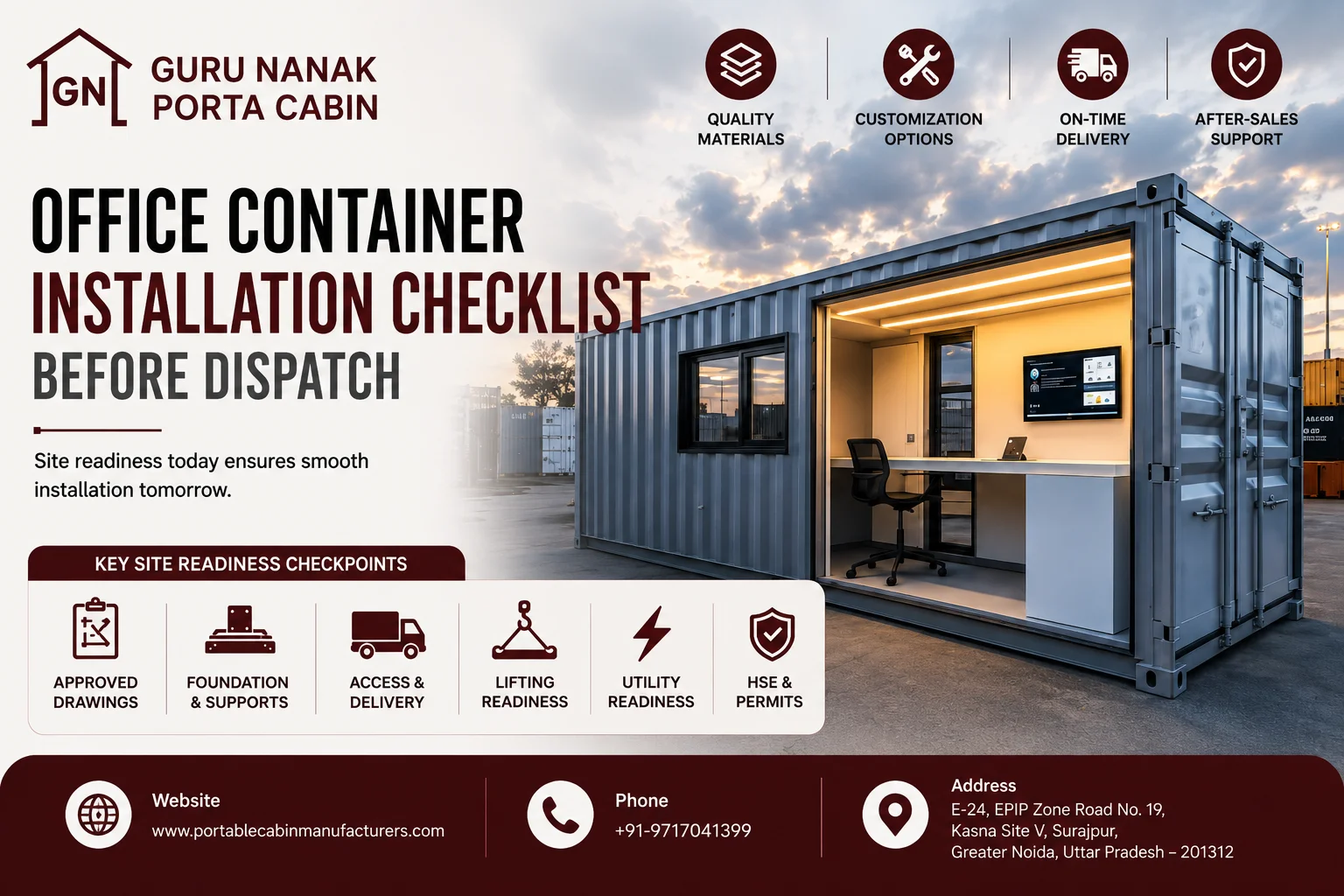
What Project Managers Should Verify Before Office Container Installation
29 Jul, 2026
An office container may leave the fabrication facility fully finished, inspected and ready for use, yet still encounter serious installation problems when it reaches the project site.
The reason is straightforward: factory readiness and site readiness are two different engineering conditions.
A container can arrive at site only to find that its supports are at different elevations, the delivery vehicle cannot clear the gate, the crane cannot establish a safe working position, an overhead cable crosses the lifting path, or the electrical and drainage connections terminate on the wrong side of the installation area.
For a project manager, therefore, office container installation should not be treated as a simple unloading activity. It should be managed as a project-readiness gate connecting civil works, logistics, lifting operations, utilities, HSE requirements and supplier responsibilities.
This office container installation checklist provides a structured framework for making that decision before dispatch is authorized.
Before authorizing office container installation, a project manager should verify the approved drawings, foundation or support arrangement, support elevations, installation-area dimensions, drainage, delivery access, crane positioning, lifting path, utility interfaces, electrical supply, earthing, HVAC requirements, anchoring requirements, HSE clearances and contractual responsibility matrix.
Installation should proceed only when critical interfaces have been verified against project requirements rather than assumed from visual inspection.
A useful readiness sequence is:
Approved drawings → Site survey → Foundation/support verification → Access verification → Lifting readiness → Utility readiness → HSE clearance → Dispatch authorization → Positioning → Inspection → Handover
Office Container Installation Is an Interface-Control Problem
The installation stage brings several independent work packages together.
The office container manufacturer controls the fabricated unit. The civil contractor may control the foundation or supports. A logistics provider controls transportation. A crane agency may perform lifting. Electrical, HVAC and plumbing contractors complete external services. The project HSE team controls permits and lifting-area safety.
The project manager has to make these interfaces work as one installation sequence.
This is why many installation problems are not caused by the office container itself. They occur at the interfaces between responsibilities.
For example, a support arrangement may be structurally suitable in principle but positioned differently from the approved container base-frame support locations. Similarly, a crane may have adequate nominal capacity while being unable to perform the lift safely at the actual operating radius.
The project manager's role is therefore to verify interfaces before they become site problems.
1. Verify Approved Documents Before Checking the Physical Site
Site verification should begin with controlled documents, not a tape measure.
The project team needs an agreed technical reference against which actual conditions can be inspected. Without that reference, statements such as "foundation ready" or "access available" are difficult to verify objectively.
Approved-Document Verification Register
| Document | Why It Matters | Verification |
|---|---|---|
| General arrangement drawing | Establishes container dimensions and configuration | Approved/current revision |
| Site layout | Establishes final installation position | Location verified |
| Foundation/support drawing | Defines support arrangement | Actual site compared |
| Electrical load schedule | Establishes supply requirement | Incoming supply reviewed |
| Utility interface drawing | Coordinates connection points | Interface locations checked |
| Installation method statement | Defines installation sequence where required | Reviewed |
| Lifting plan | Controls lifting activity where required | Approved by responsible personnel |
| Quality/inspection plan | Defines inspection stages | Available |
| Installation checklist | Records installation verification | Prepared |
| Handover checklist | Controls final acceptance | Prepared |
A common project-control failure is using an outdated drawing at site. A small revision to container dimensions, door orientation, utility entry location or module configuration can affect civil works and installation access.
Engineering checkpoint: Confirm document revision status before accepting any physical measurement as compliant.
2. Verify Foundation and Support Conditions
The foundation or supporting surface is one of the most important installation interfaces because it transfers loads from the container base into the supporting structure or ground.
A surface that appears flat is not automatically suitable.
The required support arrangement depends on the office container design, site conditions and project-specific engineering requirements. Project managers should therefore avoid assuming that every office container can be placed directly on soil, an arbitrary concrete slab or randomly positioned blocks.
Foundation and Support-Point Verification
| Check | Project Manager Should Verify |
|---|---|
| Foundation dimensions | Match approved arrangement |
| Support locations | Correspond with required base-frame support positions |
| Support elevation | Checked at all specified points |
| Bearing surface | Stable and suitable for intended support |
| Existing slab condition | No unacceptable deterioration at support areas |
| Settlement risk | Reviewed for actual site conditions |
| Drainage | Water does not collect beneath the container |
| Installation area | Clear of debris and obstructions |
| Underground services | Identified before civil or anchoring activity |
| Anchoring interface | Prepared where anchoring is required |
Why Support Elevation Matters
Uneven supports can cause the container base frame to bear unevenly.
Possible consequences include:
- rocking or instability,
- local concentration of reactions,
- base-frame distortion,
- floor-level variation,
- door or window misalignment,
- difficulty aligning connected modules,
- joint-sealing problems.
A simple site measurement concept is:
Level difference = Highest measured support elevation − Lowest measured support elevation
Example:
If the highest measured support elevation is 100.012 m and the lowest is 100.004 m:
Level difference = 100.012 − 100.004 = 0.008 m
That is an 8 mm elevation difference.
This calculation does not determine whether 8 mm is acceptable. Acceptance must be based on the approved project requirements and responsible engineering review.
The value simply turns "the supports look level" into measurable information.
3. Do Not Assume an Existing Concrete Slab Is Automatically Suitable
An existing concrete area can simplify office container installation, but the presence of concrete alone does not establish readiness.
The project team still needs to assess whether the slab provides appropriate support at the required locations and whether its condition is compatible with the installation arrangement.
Relevant checks include:
- slab condition,
- local cracking or deterioration,
- required support locations,
- elevation differences,
- drainage,
- existing slopes,
- embedded or underground services,
- anchoring requirements,
- surrounding access.
The key distinction is between having concrete and having a verified supporting arrangement.
Foundation engineering, bearing-capacity assessment and anchoring design should remain with the competent responsible engineer where project-specific calculations are required.
4. Verify Delivery Access Before Dispatch
One of the most avoidable office container installation mistakes is discovering an access problem after the transport vehicle has already reached the project.
Delivery-route verification should cover the entire route inside the controlled project area, not merely the main entrance.
Delivery-Route and Access Checklist
| Parameter | Verification Question |
|---|---|
| Gate width | Can the loaded transport configuration pass safely? |
| Gate height | Is sufficient vertical clearance available? |
| Internal road width | Can the vehicle proceed without obstruction? |
| Turning radius | Can the transport vehicle negotiate turns? |
| Road condition | Can the route support planned movement? |
| Overhead services | Are cables, pipes or structures clear? |
| Temporary structures | Do scaffolds or barricades obstruct access? |
| Parking/staging | Is temporary vehicle positioning possible? |
| Reversing movement | Can it be managed safely? |
| Unloading point | Can the vehicle reach the planned lifting zone? |
A useful preliminary check is:
Access clearance margin = Available clearance − Required transport clearance
For example, if available gate width is 4.5 m and the project-specific transport requirement is 3.8 m:
Clearance margin = 4.5 − 3.8 = 0.7 m
That margin should not automatically be considered sufficient. Vehicle geometry, mirrors or projections, approach angle, driver manoeuvring, safety clearances and site requirements still need consideration.
Vertical Clearance Example
Suppose the verified loaded vehicle height is 4.2 m and an overhead obstruction is measured at 4.6 m.
The nominal difference is:
4.6 − 4.2 = 0.4 m
The responsible logistics and site teams must determine whether this provides acceptable operational clearance.
Measurements should support decisions, not replace professional judgement.
5. Verify Crane and Lifting Readiness
The statement "a crane is available" does not establish lifting readiness.
A safe lifting operation depends on the actual lifted load, lifting radius, crane configuration, ground conditions, outrigger arrangement, rigging, lifting points, obstructions and
competent lifting supervision.
Crane and Lifting Readiness Checklist
Verify:
- actual container/module weight is available,
- approved lifting points are identified,
- lifting method is defined,
- crane position is established,
- required operating radius is understood,
- crane documentation satisfies project requirements,
- outrigger space is available,
- supporting ground conditions have been reviewed,
- lifting path is clear,
- overhead electrical hazards have been assessed,
- exclusion zone can be established,
- transport vehicle and crane can occupy the area simultaneously where required,
- competent lifting personnel are assigned,
- weather restrictions are considered,
- communication arrangements are defined.
Preliminary Crane-Radius Readiness Concept
A useful conceptual expression is:
Crane capacity utilization = Required lifted load ÷ Allowable crane capacity at actual radius × 100
This formula should not be used to select a crane from generic assumptions.
Allowable capacity changes with crane configuration, boom arrangement, operating radius and other manufacturer-defined conditions. Crane selection and lifting calculations must be completed by competent lifting professionals using actual project information and applicable procedures.
For the project manager, the important question is not:
"What is the crane's maximum capacity?"
It is:
"Has the planned lifting arrangement been verified for the actual site geometry and operating condition?"
6. Check the Installation Zone, Not Just the Container Footprint
The required working area extends beyond the external dimensions of the office container.
Installation may require temporary space for:
- transport vehicle positioning,
- crane setup,
- outriggers,
- rigging personnel,
- exclusion zones,
- module manoeuvring,
- HVAC installation,
- electrical and plumbing work,
- joint sealing,
- access steps or platforms,
- future maintenance.
Installation-Zone Dimensional Check
Suppose a container requires a nominal footprint of 12 m × 3 m, while the available installation zone is 14 m × 5 m.
The apparent side clearance is not sufficient evidence of readiness. The project manager must still verify whether the remaining space accommodates installation activities, access, utilities, emergency movement and any required maintenance clearances.
This is particularly important where office containers are installed between buildings, boundary walls, equipment foundations or active construction zones.
7. Verify Drainage Before Positioning the Container
Drainage is frequently treated as a secondary civil issue, but poor drainage can directly affect installation quality and long-term condition.
Water should not be allowed to accumulate beneath the office container or repeatedly flow toward support locations.
Project managers should verify:
- finished ground levels,
- surface-water direction,
- low points,
- roof-water discharge path,
- nearby drains,
- erosion potential,
- support-area drainage,
- splashback or standing-water exposure.
A simple drainage-slope concept is:
Slope = Vertical fall ÷ Horizontal distance
This concept can help teams understand drainage direction, but the required drainage design should be determined according to actual site conditions and project requirements.
The objective is straightforward: surface water should be intentionally managed rather than allowed to find its own path around the installed unit.
8. Verify Utility Interfaces Before Delivery
A container should not be positioned first and utility coordination attempted afterwards.
The external utility interfaces should be checked against the approved container layout before installation.
Utility-Interface Readiness Table
| Utility | Verify Before Installation |
|---|---|
| Electrical supply | Capacity, voltage/system requirements and connection location |
| Earthing | Approved earthing arrangement available |
| Water | Supply point location and accessibility |
| Wastewater | Drain connection/discharge arrangement available |
| HVAC | Outdoor-unit position and clearance |
| Data/communications | Entry route if required |
| External lighting | Interface requirement where applicable |
| Drainage | Roof and surrounding surface-water route |
Electrical Capacity Concept
A preliminary project-management check can be expressed as:
Utility capacity margin = Available capacity − Estimated operating demand
If 25 kW is available at the designated supply and estimated connected operating demand is 18 kW:
Preliminary margin = 25 − 18 = 7 kW
This is only an illustrative coordination check. Electrical design must consider actual loads, diversity where applicable, protective devices, cable sizing, earthing, starting characteristics and applicable project specifications, statutory requirements and relevant Indian Standards.
Electrical work should be completed and verified by competent personnel.
9. Confirm Earthing Before Occupancy
Electrical readiness is more than having an incoming cable near the container.
The project team should verify the complete electrical interface, including:
- incoming supply availability,
- approved connection arrangement,
- distribution-board readiness,
- protective devices,
- cable routing,
- earthing arrangement,
- continuity checks,
- lighting functionality,
- socket functionality,
- HVAC supply where applicable,
- electrical test documentation.
Where electrical installation requirements are governed by project specifications or statutory provisions, these should be reviewed by the responsible electrical professional.
An office container should not be considered operationally ready simply because its internal lights switch on.
10. Coordinate HVAC Location Before Final Positioning
HVAC problems often arise because indoor equipment locations were considered during fabrication while the external environment was not fully coordinated.
Before installation, check:
- outdoor-unit position,
- service clearance,
- airflow clearance,
- condensate drainage,
- electrical supply,
- piping route,
- interference with adjacent structures,
- future maintenance access.
A container installed tightly against another structure may make a previously acceptable HVAC arrangement difficult to install or maintain.
This is why site geometry should be reviewed together with the container configuration, not separately.
11. Determine Whether Anchoring Is Required
The weight of an office container should not be used as a universal argument against anchoring.
Anchoring requirements depend on the project-specific structural arrangement, environmental conditions, support system and responsible engineering assessment.
Relevant factors may include:
- wind exposure,
- site location,
- container geometry,
- support arrangement,
- installation duration,
- surrounding exposure,
- modular configuration,
- project structural requirements.
Where anchoring is required, verify the interface before installation rather than improvising an anchoring solution after positioning.
Any final anchoring design, structural calculation, wind-load assessment or foundation design should be verified by the competent responsible engineer using actual project data.
12. Define Supplier Versus Client Scope Before Mobilization
A technically ready site can still suffer delays if commercial responsibilities are unclear.
The quotation, purchase order or installation scope should state who provides each activity.
Typical Installation Responsibility Matrix
| Activity | Responsibility Must Be Defined For |
|---|---|
| Foundation/support construction | Client / civil contractor / supplier if contracted |
| Site survey | Agreed responsible party |
| Transport | Supplier or logistics provider |
| Gate/access readiness | Client/site team |
| Crane/hydra | Supplier or client as contracted |
| Rigging | Defined lifting contractor |
| Positioning | Installation team |
| Anchoring | Defined contractual party |
| Electrical incoming supply | Usually project-side interface unless contracted otherwise |
| External electrical connection | Defined electrical contractor |
| Earthing | Defined project/supplier scope |
| Water supply | Project-side interface unless included |
| Wastewater connection | Defined plumbing/civil scope |
| HVAC installation | Defined supplier/project scope |
| HSE permits | Site procedure responsibility |
| Final inspection | Supplier + project/client representatives as applicable |
| Snag closure | Responsible party based on defect/interface |
This table is intentionally not prescriptive because contracts differ.
Its purpose is to expose undefined interfaces before mobilization.
13. Establish Installation Hold Points
A hold point prevents the next stage from proceeding until defined conditions are verified.
For office container installation, practical hold points can significantly reduce rework.
Suggested Installation Hold-Point Checklist
Hold Point 1 – Documents
Approved drawings and current revisions available.
Hold Point 2 – Civil Readiness
Foundation/support arrangement physically verified.
Hold Point 3 – Access
Delivery route and unloading zone confirmed.
Hold Point 4 – Lifting
Lifting arrangement cleared according to project procedures.
Hold Point 5 – Utilities
Required utility interfaces identified and accessible.
Hold Point 6 – HSE
Site permits, exclusion zone and installation safety arrangements ready.
Hold Point 7 – Dispatch Authorization
Project manager confirms critical prerequisites are closed.
Hold Point 8 – Post-Positioning
Level, alignment, support and condition verified.
Hold Point 9 – Utility Commissioning
Electrical, HVAC and plumbing systems checked where applicable.
Hold Point 10 – Handover
Snags and required documentation closed.
The strongest hold point is often dispatch authorization because it prevents a finished unit from arriving at an unprepared site.
14. Use a GO / CONDITIONAL GO / NO-GO Decision
A binary "ready/not ready" decision can be too simplistic for complex project sites.
A three-level framework provides better control.
Installation Decision Matrix
| Status | Meaning | Action |
|---|---|---|
| GO | Critical site, support, access, lifting, utilities, HSE and documentation requirements verified | Authorize installation |
| CONDITIONAL GO | Minor non-safety-critical issues remain with defined owners and closure dates | Proceed only under documented controls |
| NO-GO | Critical support, lifting, access, structural interface, electrical safety or approval issues unresolved | Do not authorize installation |
A missing cosmetic item may justify a Conditional Go.
An unverified lifting arrangement, incorrect support configuration or unsafe electrical interface should not be treated in the same category.
The decision framework forces project teams to distinguish inconvenience from genuine installation risk.
15. Check Multi-Module Alignment Before Joining Units
Where multiple office container modules form a larger project office, individual placement accuracy becomes even more important.
Small positioning errors can accumulate across modules.
Verify:
- support coordinates,
- support elevations,
- module orientation,
- base-frame alignment,
- interface gaps,
- floor continuity,
- roof interface,
- joint sealing,
- flashing,
- utility interconnections.
A useful concept is to compare actual module position against the approved layout rather than aligning each new module only to the previously installed unit.
Otherwise, incremental errors can propagate through the complete modular arrangement.
Acceptance tolerances must come from approved project requirements rather than generic assumptions.
16. Inspect Immediately After Positioning
Installation does not finish when the crane releases the load.
Post-positioning inspection should begin before utility commissioning or occupancy.
Post-Positioning Inspection Checklist
Check:
- container orientation,
- support contact,
- level and alignment,
- visible base-frame condition,
- exterior transport damage,
- roof condition,
- coating damage,
- doors,
- windows,
- floor condition,
- internal partitions,
- module joints,
- sealants and flashing,
- anchoring where applicable,
- electrical condition,
- HVAC condition,
- plumbing interfaces,
- drainage arrangement.
Doors and windows can act as useful indicators of installation distortion. If a previously functional door becomes difficult to operate after positioning, support conditions and frame alignment should be investigated rather than immediately modifying the door.
17. Record Transport and Installation Damage Before Handover
Damage documentation should distinguish between:
- pre-existing fabrication snag,
- transportation damage,
- unloading damage,
- installation damage,
- subsequent site damage.
Photographic records taken before unloading and after positioning provide useful traceability.
This protects both the project team and supplier from later disagreement about when a defect occurred.
For projects using formal quality systems, installation records can be incorporated into the applicable inspection and test documentation.
Common Office Container Installation Mistakes and Preventive Actions
| Installation Mistake | Potential Effect | Preventive Action |
|---|---|---|
| Dispatch before civil readiness | Waiting time and remobilization | Use dispatch hold point |
| Incorrect support locations | Improper load transfer | Verify against approved drawing |
| Uneven supports | Distortion or instability | Measure elevations |
| Unverified access | Delivery failure | Conduct route survey |
| Crane selected only by nominal capacity | Unsafe/impractical lift | Verify actual lift conditions |
| No outrigger space | Crane cannot establish safely | Mark crane setup area |
| Overhead cable ignored | Serious lifting hazard | Survey lifting path |
| Utilities on wrong side | Rework | Coordinate interface drawing |
| Poor site drainage | Standing water around supports | Verify finished levels |
| Anchoring assumed unnecessary | Structural risk where required | Obtain project-specific review |
| No transport-damage record | Handover disputes | Photograph before/after unloading |
| Occupancy before snag closure | Operational defects remain | Formal handover inspection |
Office Container Pre-Installation Master Checklist
Before authorizing dispatch, the project manager should be able to answer yes to the critical items below.
Documentation
- Approved GA drawing available
- Site layout approved
- Foundation/support arrangement confirmed
- Utility requirements coordinated
- Installation responsibilities defined
- Required HSE documentation available
Civil and Foundation
- Installation coordinates verified
- Supports constructed at correct locations
- Elevations measured
- Supporting surfaces reviewed
- Installation zone clear
- Drainage condition acceptable
- Underground services identified where relevant
Logistics
- Gate width verified
- Gate height verified
- Internal roads checked
- Turning requirements reviewed
- Transport staging identified
- Unloading location available
Lifting
- Module weight confirmed
- Lifting points identified
- Crane position planned
- Working radius reviewed
- Outrigger area available
- Ground conditions reviewed by responsible parties
- Lifting path clear
- Exclusion zone possible
- Required lifting approvals complete
Utilities
- Incoming electricity available
- Electrical interface coordinated
- Earthing arrangement available
- Water interface ready where required
- Drainage/wastewater interface ready
- HVAC outdoor-unit space available
Installation
- Positioning sequence defined
- Module alignment approach established
- Anchoring requirement confirmed
- Joint-sealing responsibility assigned
- Post-positioning inspection planned
- Snag process established
If a critical item cannot be positively verified, the project manager should identify it as an open installation constraint rather than relying on an assumption.
Installation Schedule Readiness Matters Too
Physical readiness is only one part of installation planning.
Civil completion, transport booking, crane availability, HSE permits and utility teams must converge on the same installation window.
A simple scheduling concept is:
Installation schedule float = Required delivery date − Latest site-readiness completion date
Suppose delivery is planned for 20 August and all critical site-readiness activities must be complete by 17 August.
That provides three calendar days between planned readiness and delivery.
Whether that float is adequate depends on project risk, inspection requirements and the reliability of preceding activities.
The key project-management principle is to avoid scheduling dispatch against an optimistic civil-completion assumption.
Which Requirements and Standards Should Be Reviewed?
Office container installation should be evaluated against applicable project specifications, statutory requirements and relevant Indian Standards.
Depending on project conditions, the responsible engineering team may need to review:
- structural design and fabrication requirements,
- wind and seismic provisions,
- electrical installation and earthing requirements,
- fire and life-safety requirements,
- National Building Code provisions where applicable,
- local temporary-structure requirements,
- workplace HSE requirements,
- EPC/client specifications,
- transportation restrictions,
- manufacturer-approved installation procedures.
Individual code references should be verified by the responsible project engineer rather than assumed to apply universally.
Final Installation Acceptance Should Be Evidence-Based
A project manager should be able to trace final acceptance back to documented verification.
Useful handover records may include:
- approved drawings,
- installation checklist,
- foundation/support verification record,
- inspection records,
- lifting documentation where required,
- electrical test records,
- utility commissioning records,
- snag register,
- photographic records,
- warranty documentation,
- maintenance instructions.
The exact documentation package depends on project requirements and contractual scope.
The important principle is that handover should represent verified readiness for use, not merely completion of physical positioning.
Technical Decision: When Should Dispatch Be Authorized?
Dispatch should be authorized when critical site interfaces have moved from assumptions to verified conditions.
A technically strong dispatch decision answers five questions:
- Can the container reach the installation location?
- Can it be lifted and positioned under an approved safe arrangement?
- Can the prepared supports receive it as designed?
- Can required utilities and drainage be connected without avoidable rework?
- Are responsibilities, HSE requirements and acceptance criteria understood?
If one of these remains unresolved, the project manager should determine whether the issue represents a Conditional Go or a genuine No-Go condition.
That discipline is more valuable than trying to accelerate installation by a few hours and then losing days to remobilization or rework.
Engineering FAQs
1. Does every office container require a concrete foundation?
Not necessarily. The required support arrangement depends on the container design, site conditions, loading, installation duration and project engineering requirements. The project team should use the approved support or foundation arrangement rather than assuming that one foundation type suits every office container.
2. Can an office container be installed directly on existing concrete?
Potentially, but the existing concrete should be assessed for condition, level, support locations, drainage and project-specific requirements. The presence of a slab does not by itself confirm that the installation interface is suitable.
3. Why should support elevations be measured?
Support elevation differences can create uneven bearing and affect container level, frame alignment, floor condition, doors, windows and modular interfaces. Measurements provide objective evidence that can be compared with approved acceptance requirements.
4. What should be checked before dispatching an office container?
Verify approved documents, supports, installation dimensions, access route, lifting readiness, utility interfaces, HSE requirements, responsibilities and installation-zone clearance before dispatch authorization.
5. Is crane capacity the only factor in crane selection?
No. Actual lifting radius, crane configuration, ground condition, outrigger arrangement, lifting path, rigging, module weight and site restrictions also affect lifting feasibility. Crane selection should be completed by competent lifting professionals.
6. Why should the delivery route be checked before dispatch?
Container dimensions and transport geometry can make internal gates, narrow roads, turns and overhead obstructions critical. Early route verification prevents vehicles reaching the project only to discover that the unloading location is inaccessible.
7. Who should arrange the crane for office container installation?
That depends on contractual scope. The purchase order or quotation should clearly state whether the supplier, client, logistics contractor or another nominated party is responsible for crane mobilization and lifting arrangements.
8. Why is drainage important around an office container?
Poor surface drainage can allow standing water around supports and increase moisture exposure. Drainage should direct water away from the installation area and be coordinated with roof-water discharge and surrounding finished levels.
9. Should utility connections be prepared before container installation?
Their locations and requirements should at least be coordinated before positioning. Early coordination reduces cable rerouting, plumbing extensions, wall penetrations and HVAC installation conflicts after the container is in place.
10. Is anchoring always required?
Not universally. Anchoring requirements depend on project-specific structural and environmental conditions. The responsible engineer should determine the requirement using the actual installation configuration rather than assuming that container self-weight is sufficient.
11. What is an installation hold point?
An installation hold point is a defined project stage that cannot proceed until specified conditions have been verified. Examples include foundation readiness, access clearance, lifting approval and final dispatch authorization.
12. What does Conditional Go mean?
Conditional Go means installation may proceed despite minor non-safety-critical open items because those items are documented, assigned to responsible parties and subject to agreed closure deadlines.
13. What conditions should normally trigger a No-Go decision?
Unverified supports, unsafe lifting conditions, blocked access, unresolved structural interfaces, critical electrical-safety issues or missing mandatory approvals should normally prevent installation until appropriately resolved.
14. How should multiple office container modules be aligned?
Modules should be positioned against the approved layout and defined reference points. Support elevations, interface gaps, floor continuity, roof joints, sealing and utility interconnections should be checked as modules are installed.
15. Why should doors and windows be checked after positioning?
A change in door or window operation can indicate installation-related frame distortion or alignment issues. The support arrangement should be investigated before treating the problem only as a hardware adjustment.
16. Should the office container be inspected after relocation?
Yes. Relocation introduces another transport, lifting and positioning cycle. Structural condition, supports, coatings, joints, doors, windows, electrical systems and other relevant interfaces should be inspected again before use.
17. What should an installation snag register contain?
It should identify the observed issue, location, responsible party, required corrective action, status and closure evidence. Photographs can improve traceability for transport or installation-related defects.
18. When is office container installation considered complete?
Installation should be considered complete after positioning, support verification, alignment, required anchoring or interconnection, utility commissioning where applicable, functional inspection, snag closure and required handover documentation—not simply when the crane releases the container.
Project Manager's Final Installation Rule
The most useful question before an office container reaches site is not:
"Is the container ready?"
It is:
"Are all interfaces required to receive, lift, support, connect, inspect and safely use the container ready?"
That distinction changes installation from a reactive site activity into a controlled project milestone.
Foundation readiness, delivery access, lifting geometry, utility coordination, drainage, HSE controls and responsibility allocation should therefore be verified before dispatch rather than solved independently after arrival.
For projects requiring technical details on configurations and applications, review the Office Container Manufacturer page from Guru Nanak Porta Cabin. Related technical planning can also be supported through the company's Portable Cabin and prefabricated structure resources.
Request an Office Container Installation Readiness Review
Planning an office container installation for an active construction, EPC, infrastructure or industrial project?
Share your site layout, foundation or support details, delivery access conditions, utility availability and required installation schedule with Guru Nanak Porta Cabin.
The team can review project-specific requirements and provide guidance on office container configuration, delivery and installation coordination along with a customized quotation.
Contact Guru Nanak Porta Cabin through the company's Contact Us page.


