

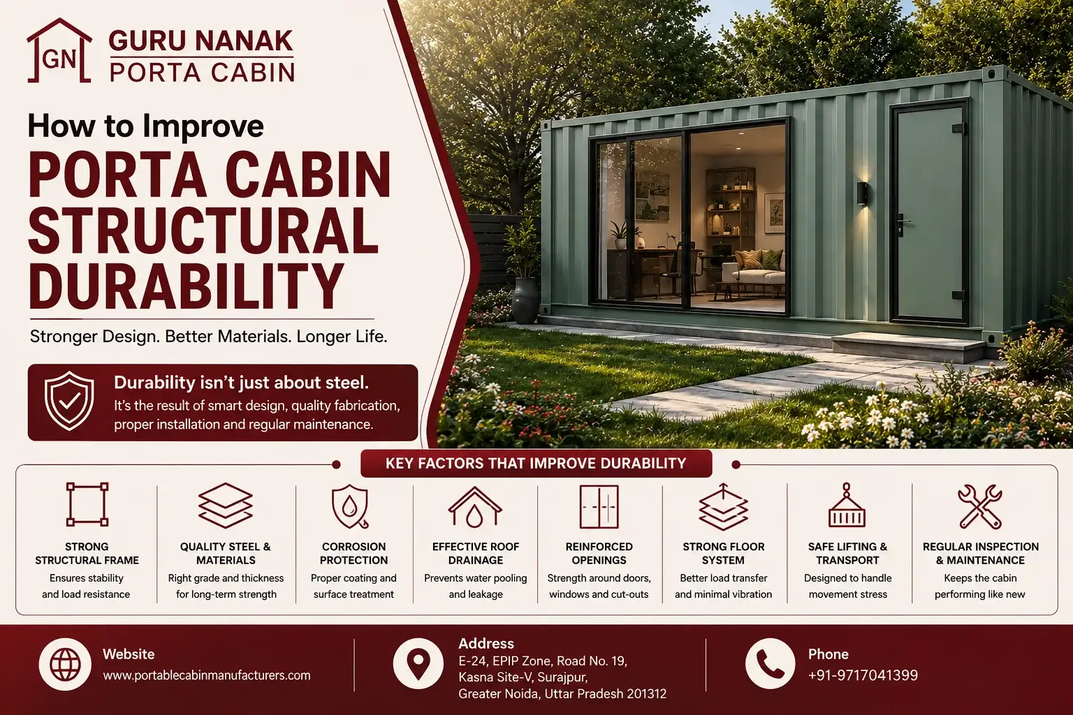
Structural Design Factors That Improve Porta Cabin Durability
08 Aug, 2026
A porta cabin does not become durable simply because it is manufactured from steel.
Its long-term performance depends on how the structural frame carries load, how openings are reinforced, how the floor transfers occupancy loads, how the roof drains water, how joints are sealed, how corrosion is controlled and how the cabin is lifted, transported, installed and maintained.
Two porta cabins may appear nearly identical from the outside yet perform very differently in service. One may remain aligned after repeated relocation, while another develops distorted door frames, floor vibration, roof leakage or panel separation. These differences usually originate in structural design, fabrication quality, material protection or installation—not appearance alone.
For project engineers and procurement teams, durability should therefore be evaluated as an engineering outcome. The cabin must be designed for its dimensions, occupancy, equipment, climate, transportation route, lifting method and expected relocation frequency.
Guru Nanak Porta Cabin supports project-specific frame detailing, steel fabrication, material selection, insulation planning, protective coating and installation coordination. Even so, the final design must always be reviewed against applicable project specifications, statutory requirements and relevant Indian Standards.
Porta cabin durability improves when the structural frame provides a clear load path, adequate member stiffness, reinforced openings, stable floor supports, effective roof drainage, controlled joints, corrosion-resistant detailing and safe lifting provisions. Durability also depends on fabrication accuracy, protective coating, foundation support, transport handling, inspection and preventive maintenance.
1. What Structural Durability Means in a Porta Cabin
Structural durability is the ability of a porta cabin to maintain stability, alignment, weather tightness and functional performance throughout manufacturing, transportation, installation, occupancy, maintenance and relocation.
Durability does not mean that no maintenance will ever be required. It means the cabin has been designed and fabricated so that expected loads, environmental exposure and handling do not cause premature deterioration or loss of function.
A Durable Porta Cabin Should Maintain
- Frame alignment
- Floor stiffness
- Roof drainage
- Door and window operation
- Panel-joint integrity
- Structural stability
- Coating continuity
- Weather tightness
- Safe lifting capability
- Support-point stability
- Utility alignment
- Maintainability after relocation
Durability Is a System Property
A strong steel column cannot compensate for:
- Weak floor supports
- Poorly reinforced openings
- Inadequate roof slope
- Discontinuous welding
- Unsealed joints
- Improper lifting
- Uneven foundations
- Uncontrolled corrosion
The entire cabin must work as one structural and enclosure system.
2. Start With a Complete Load Path
A load path is the route through which forces travel from the point of application to the cabin supports or foundation.
In a well-designed porta cabin, roof loads, wall loads, floor loads, equipment loads and handling forces are transferred through connected structural members without creating uncontrolled local deformation.
Typical Load Path
Roof sheeting
↓
Roof purlins or secondary supports
↓
Main roof frame
↓
Vertical frame members
↓
Base frame
↓
Support points or foundation
Floor finish
↓
Flooring substrate
↓
Floor joists or cross-members
↓
Base frame
↓
Supports
Why Load-Path Continuity Matters
When a member is added without considering how its load reaches the base frame, stress can concentrate around:
- Door openings
- Window corners
- Partition intersections
- AC openings
- Plumbing penetrations
- Lifting brackets
- Module-connection points
A structurally durable cabin avoids abrupt load-transfer interruptions.
Engineering Checkpoint
Before approving the structural design, verify that roof, floor, opening, lifting and equipment loads have identifiable paths to the supports.
3. Main-Frame Geometry and Member Arrangement
The main structural frame determines the cabin’s resistance to bending, twisting and permanent distortion.
Its geometry should reflect the cabin’s length, width, height, opening pattern, internal layout and transportation requirements.
Important Frame Elements
- Longitudinal base members
- Transverse floor members
- Corner posts
- Intermediate wall studs
- Top longitudinal members
- Roof cross-members
- Bracing
- Opening reinforcement
- Lifting reinforcements
- Modular connection members
Long Cabins Need More Than Larger Outer Members
Increasing cabin length without reviewing intermediate support spacing may result in:
- Floor deflection
- Roof deflection
- Wall vibration
- Joint movement
- Door misalignment
Intermediate members help control unsupported spans, but their position must coordinate with partitions, furniture, electrical routes and openings.
Squareness Matters
A cabin may be structurally stable yet difficult to finish if the frame is not square.
Loss of squareness can lead to:
- Unequal panel gaps
- Misaligned doors
- Window jamming
- Flooring mismatch
- Modular joint misalignment
Frame geometry should therefore be checked before wall panels, flooring and interior finishes conceal the primary structure.
4. Steel Selection and Section Configuration
Steel selection should be based on structural demand, fabrication suitability, environmental exposure and expected relocation.
No single steel thickness or section is suitable for every porta cabin.
Factors Influencing Steel Selection
- Cabin dimensions
- Floor loading
- Roof loading
- Number of openings
- Equipment loads
- Wind exposure
- Transportation frequency
- Lifting arrangement
- Corrosion environment
- Future modification
Section Shape Matters
Structural behaviour depends not only on material quantity but also on section geometry.
A correctly oriented section can provide greater stiffness than a poorly oriented heavier member.
Engineers should consider:
- Bending direction
- Torsional resistance
- Connection access
- Welding access
- Water-trap risk
- Coating access
- Availability of replacement material
Material Selection Trade-Off
Heavier steel may improve stiffness, but unnecessary weight can increase:
- Transport load
- Crane requirement
- Lifting stress
- Foundation demand
- Handling complexity
The design objective is adequate structural performance with practical manufacturability and safe transport—not maximum steel weight.
5. Base-Frame Stiffness and Floor Performance
The base frame carries occupancy, furniture, partitions, equipment and the cabin’s self-weight.
Poor base-frame design often appears as floor vibration, sagging, uneven finishes or door misalignment.
Floor System Components
- Longitudinal base rails
- Cross-members
- Floor-support framing
- Flooring substrate
- Finished flooring
- Local equipment reinforcement
What Affects Floor Stiffness?
- Cross-member spacing
- Member depth
- Member orientation
- Support spacing
- Flooring substrate
- Joint quality
- Concentrated equipment loads
- Moisture exposure
Dead Load and Live Load
Dead load is the permanent weight of the cabin structure, flooring, partitions and fixed services.
Live load includes occupants, movable furniture, stored files and temporary equipment.
The responsible engineer must evaluate both categories using verified project requirements. Generic occupancy assumptions should not replace a defined equipment and furniture schedule.
Simplified Floor-Area Illustration
For a cabin with external length (L) and width (W):
Footprint area = L × W
This calculation identifies overall area only. It does not determine floor-member size, support spacing or allowable load.
Local Reinforcement
Heavy items such as:
- Battery systems
- Server racks
- Filing cabinets
- Water tanks
- Laboratory equipment
- Electrical panels
may require localized reinforcement rather than a uniform increase across the entire floor.
6. Roof Framing, Slope and Drainage
A durable porta cabin roof must carry applied loads while draining water without excessive deflection or ponding.
Roof leakage is often blamed on sheet material, but the root cause may be insufficient slope, frame deflection, poor flashing, damaged fasteners or blocked drainage.
Roof Design Considerations
- Roof-member spacing
- Roof slope
- Sheet support
- Joint direction
- Ridge detailing
- Edge flashing
- Gutter arrangement
- Rainwater discharge
- Equipment penetrations
- Maintenance access
Simplified Roof-Slope Illustration
Roof slope can be expressed as:
Rise ÷ horizontal run
The required slope must be determined from the selected roofing system, drainage arrangement and project conditions. A simplified ratio should not be used as a construction instruction without engineering verification.
Water Ponding Risk
Water ponding can increase local roof load and worsen deflection.
Potential causes include:
- Insufficient slope
- Long unsupported roof spans
- Incorrect frame levels
- Drain blockage
- Deformed roofing
- Settlement of supports
- Poor installation
Durability Principle
The roof structure, sheet profile, fasteners, sealants and drainage path must be treated as one coordinated system.
7. Reinforcement Around Doors and Windows
Doors and windows interrupt structural members and change the way loads flow through the wall frame.
Openings should therefore be integrated during design rather than cut into completed framing without review.
Opening Reinforcement May Include
- Header members
- Side jamb reinforcement
- Lower sill support
- Corner stiffening
- Local bracing
- Load-transfer members
Common Problems Around Openings
- Cracking or coating damage at corners
- Door-frame distortion
- Window misalignment
- Sheet vibration
- Water entry
- Reduced wall stiffness
Door Loads Are Not Static Only
Doors also introduce operational forces through:
- Repeated opening and closing
- Slamming
- Wind pressure
- Hardware loads
- Door-closer forces
Large doors or double-leaf arrangements require greater attention than small personnel doors.
Engineering Checkpoint
Any opening added after fabrication should trigger a structural review rather than being treated as a simple sheet-metal modification.
8. Wall Framing and Panel Support
Wall framing supports cladding, insulation, internal lining, doors, windows and attached services.
Adequate support spacing reduces sheet vibration, panel deformation and joint movement.
Wall-System Functions
- Transfer wind pressure
- Support panels
- Maintain alignment
- Carry internal lining
- Support service points
- Resist handling vibration
- Preserve weather tightness
Panel Support Issues
Panels can deform or separate when:
- Support spacing is excessive
- Fasteners are incorrectly placed
- Frame alignment is poor
- Thermal movement is restrained
- Openings are inadequately reinforced
- Transport vibration is not considered
Interior Partitions
Internal partitions may also contribute localized loads.
Their connection points should coordinate with:
- Floor members
- Roof framing
- Electrical services
- HVAC outlets
- Door clearances
A partition should not be attached only to lightweight lining where repeated use or door movement can create instability.
9. Connections, Welding and Fastening
Structural members perform only as well as their connections.
Welded and bolted joints must transfer expected forces while remaining accessible for inspection and maintenance.
Welding Considerations
- Joint preparation
- Fit-up
- Weld continuity
- Distortion control
- Access
- Surface cleaning
- Coating restoration
- Visual inspection
Excessive Welding Is Not Automatically Better
Overwelding can create:
- Heat distortion
- Residual stress
- Difficult coating access
- Unnecessary weight
- Rework
The weld arrangement should match the structural requirement and approved fabrication procedure.
Fastened Connections
Mechanical fasteners are used in:
- Cladding
- Modular joints
- Removable panels
- Access covers
- Roof accessories
Fastener durability depends on:
- Correct type
- Correct spacing
- Washer condition
- Sealing
- Tightening
- Corrosion compatibility
Joint Inspection
Important joints should be checked before finishes hide them.
Inspection may include:
- Visual weld examination
- Dimensional verification
- Connection alignment
- Fastener presence
- Coating repair
- Sealant continuity
10. Bracing and Resistance to Distortion
Bracing helps the porta cabin resist racking, twisting and movement during transport, lifting and service.
A cabin may carry vertical loads adequately yet distort laterally if its bracing system is incomplete.
Bracing Functions
- Maintain frame geometry
- Transfer lateral loads
- Control racking
- Stabilize long wall frames
- Support transport resistance
- Preserve door and window alignment
Bracing Coordination
Bracing must not conflict with:
- Windows
- Doors
- Electrical panels
- Plumbing
- HVAC openings
- Internal circulation
- Modular connections
Removing a brace to accommodate an opening without redesign can reduce structural stability.
Transport-Induced Distortion
Road transport can introduce vibration and dynamic movement that differ from normal occupied conditions.
The structure should therefore remain stable when:
- Lifted
- Loaded onto a vehicle
- Restrained during transit
- Unloaded
- Positioned on supports
11. Corrosion Protection and Moisture Control
Corrosion protection is essential because loss of steel thickness and coating failure can reduce durability over time.
The required protection system depends on exposure, surface preparation, drainage and maintenance accessibility.
Corrosion Risk Areas
- Base-frame underside
- Weld zones
- Cut edges
- Fastener holes
- Roof joints
- Water traps
- Door thresholds
- Plumbing areas
- Coastal exposure
- Industrial pollution zones
Protective-System Components
- Surface preparation
- Primer
- Intermediate coating
- Finish coating
- Edge treatment
- Weld touch-up
- Sealants
- Drainage detailing
Water Traps
Structural details should avoid pockets where water, mud or debris can remain.
Typical risk points include:
- Open-ended sections
- Horizontal ledges
- Unsealed overlaps
- Base members near ground
- Poorly drained roof edges
Material Decision
Galvanized, coated or painted steel components may be used depending on project requirements. No material should be described as universally corrosion-proof.
12. Insulation and Condensation Management
Insulation improves thermal performance, but durability also depends on continuity, moisture control and correct installation.
Condensation can damage internal lining, electrical systems, insulation and steel surfaces even when external rainwater does not enter.
Condensation Risk Increases With
- High occupancy
- Poor ventilation
- High humidity
- Temperature differences
- Discontinuous insulation
- Unsealed penetrations
- Cold metal bridges
- Plumbing leaks
Insulation-System Durability
The system should consider:
- Material suitability
- Thickness
- Density
- Vapour movement
- Joint treatment
- Compression
- Water absorption
- Fire and project requirements
- Maintainability
Thermal Bridging
Structural steel can conduct heat across the building envelope.
A technically sound insulation layout should minimize uncontrolled gaps around:
- Frames
- Fasteners
- Doors
- Windows
- Roof-wall junctions
- Service penetrations
13. Lifting Points and Transportation Loads
Lifting points should be designed as structural load-transfer locations, not added as convenient hooks after fabrication.
Incorrect lifting can permanently distort the base frame, roof frame or wall geometry.
Lifting Design Should Consider
- Cabin weight
- Centre of gravity
- Number of lifting points
- Sling angle
- Lifting equipment
- Member capacity
- Local reinforcement
- Handling sequence
- Internal equipment
- Repeated relocation
Why Centre of Gravity Matters
A cabin with:
- Washroom
- Pantry
- Heavy electrical panel
- AC equipment
- Storage
- Uneven furniture
may not have a centrally balanced weight distribution.
The lifting arrangement must reflect the actual completed cabin, not only the empty structural shell.
Transport Restraint
Tie-down forces should be transferred through suitable structural locations.
Restraints attached to lightweight sheets or unsuitable projections may cause localized damage.
Decision Checkpoint
Before dispatch, verify lifting-point location, cabin weight, centre-of-gravity assumptions and handling method.
14. Support Points, Foundations and Settlement
A durable cabin requires uniform and stable support.
An adequately designed frame can still distort when placed on uneven, weak or settling supports.
Support Conditions Affect
- Base-frame alignment
- Floor level
- Door operation
- Wall squareness
- Roof drainage
- Modular joints
- Utility connections
Typical Support Approaches
- Concrete pads
- Pedestals
- Prepared slab
- Steel supports
- Project-specific foundations
The responsible civil or structural engineer should determine the suitable arrangement based on:
- Cabin weight
- Support reactions
- Soil condition
- Drainage
- Wind exposure
- Anchorage requirement
- Relocation plans
Uneven Settlement Symptoms
- Doors not closing
- Cracked sealant
- Sloping floor
- Panel separation
- Roof-water accumulation
- Misaligned modular joints
Support-level verification should therefore form part of installation and maintenance inspection.
15. Modular Joints and Expansion Capability
Multi-module porta cabins require joints that transfer load while maintaining weather tightness and alignment.
The connection must account for structural movement, installation tolerance and maintenance access.
Modular-Joint Requirements
- Frame alignment
- Load sharing
- Controlled tolerances
- Weather sealing
- Roof flashing
- Floor-level continuity
- Electrical coordination
- Plumbing coordination
- Disassembly access
Expansion Planning
Future expansion becomes easier when the original design provides:
- Defined connection faces
- Removable wall panels
- Service extension routes
- Structural capacity review
- Foundation space
- Drainage continuity
Expansion should not be assumed merely because the cabin is modular. The original frame and service layout must support it.
16. Fabrication Tolerances and Dimensional Control
Fabrication accuracy affects structural alignment, finish quality and installation speed.
Small errors can accumulate across the frame, panels, openings and modular joints.
Important Quality Parameters
- External dimensions
- Internal clear dimensions
- Frame squareness
- Member alignment
- Opening position
- Floor flatness
- Roof level
- Support-point alignment
- Door and window fit
- Modular interface position
Stage-Wise Dimensional Verification
Recommended inspection stages include:
- Base-frame assembly
- Vertical-frame installation
- Roof-frame completion
- Opening reinforcement
- Panel installation
- Flooring installation
- Final pre-dispatch inspection
Inspection using calibrated instruments should be performed where required by the project quality plan.
17. Structural Inspection and Testing
Inspection verifies whether the fabricated cabin matches approved drawings, specifications and quality requirements.
Testing does not create durability by itself; it confirms whether design and manufacturing controls were followed.
Typical Inspection Activities
- Approved-drawing comparison
- Incoming-material verification
- Dimensional inspection
- Weld visual inspection
- Surface-preparation inspection
- Coating inspection
- Door and window operation
- Floor-level check
- Roof-joint inspection
- Water-ingress testing
- Electrical functional checks
- Final snag inspection
Structural Inspection Table
| Inspection Point | What It Verifies | Durability Relevance |
|---|---|---|
| Frame squareness | Dimensional alignment | Prevents panel and opening misalignment |
| Weld continuity | Connection quality | Supports load transfer |
| Opening reinforcement | Local frame integrity | Reduces distortion around doors and windows |
| Floor level | Base-frame alignment | Prevents vibration and uneven loading |
| Roof slope | Drainage path | Reduces ponding and leakage risk |
| Coating coverage | Surface protection | Limits corrosion initiation |
| Lifting points | Handling readiness | Reduces transport distortion |
| Support locations | Installation compatibility | Supports stable load transfer |
Standards Language
The design and inspection process should be reviewed against applicable project specifications, statutory requirements and relevant Indian Standards.
Individual codes should be identified and verified by the responsible engineer instead of being assumed universally applicable.
18. Common Structural Failure Modes
Structural problems should be classified by root cause rather than treated as isolated defects.
Failure-Mode Table
| Observed Problem | Possible Root Cause | Engineering Response |
|---|---|---|
| Door misalignment | Frame distortion or settlement | Check squareness, supports and opening reinforcement |
| Floor vibration | Excessive member spacing or weak substrate | Review floor framing and loading |
| Roof ponding | Low slope, deflection or uneven support | Inspect roof frame and cabin level |
| Wall-panel movement | Inadequate support or fastening | Review framing and fastener layout |
| Corrosion at welds | Poor preparation or coating repair | Restore protection and inspect material loss |
| Cracked sealant | Joint movement or poor application | Correct movement source before resealing |
| Cabin twisting after relocation | Improper lifting or inadequate bracing | Conduct structural and alignment inspection |
| Window jamming | Opening distortion | Check reinforcement and support settlement |
| Base-frame corrosion | Ground moisture or trapped water | Improve clearance, drainage and coating |
| Modular joint leakage | Misalignment or flashing failure | Realign, reseal and review joint detail |
Failure Categories
Design Failure
The design does not adequately address load, geometry or environment.
Manufacturing Failure
The approved design is not fabricated accurately.
Installation Failure
Supports, anchoring, alignment or sealing are incorrect.
Operational Failure
The cabin is overloaded, modified or used outside the intended condition.
Maintenance Failure
Coating damage, leakage or settlement remains uncorrected.
19. Durability Design for Different Environments
Porta cabin structural design should respond to the actual operating environment.
Heavy Monsoon Regions
Priorities include:
- Roof drainage
- Joint sealing
- Elevated support
- Flashing
- Corrosion protection
- Regular drainage inspection
High-Temperature Sites
Consider:
- Roof insulation
- Ventilation
- Thermal movement
- Coating stability
- HVAC loading
- Internal heat gain
Coastal or Corrosive Locations
Review:
- Coating system
- Material compatibility
- Fasteners
- Cut-edge protection
- Maintenance access
- Water traps
Dusty Industrial Sites
Priorities include:
- Sealed joints
- Maintainable ventilation
- Protected electrical systems
- Easy-to-clean surfaces
- Inspection access
Frequent-Relocation Projects
Durability depends strongly on:
- Lifting design
- Bracing
- Base-frame stiffness
- Removable connections
- Repairable finishes
- Post-relocation inspection
20. Maintenance Practices That Preserve Structural Life
Maintenance should focus on early identification of water entry, corrosion, movement and alignment problems.
Recommended Inspection Areas
- Base-frame underside
- Support points
- Anchor connections
- Roof joints
- Flashings
- Sealants
- Gutters
- Door frames
- Window frames
- Coating damage
- Lifting points
- Modular joints
- Floor condition
After Relocation
A structural inspection should review:
- Frame squareness
- Floor level
- Door and window operation
- Roof alignment
- Joint condition
- Lifting-point condition
- Transport damage
- Coating damage
- Support alignment
Maintenance Principle
Repairing coating damage or failed sealant early is more effective than waiting for visible corrosion, water damage or frame distortion.
Inspection intervals should be established according to project conditions, manufacturer guidance and operating environment rather than using an unsupported universal schedule.
21. Engineering Decision Framework
Use the following framework when reviewing a proposed porta cabin design.
| Review Outcome | When It Applies | Required Action |
|---|---|---|
| Design Approved | Structure, materials and interfaces meet the defined requirement | Proceed to controlled fabrication |
| Minor Design Revision Required | Small layout or detailing conflict exists | Revise drawings before fabrication |
| Material Upgrade Recommended | Exposure or operating conditions exceed the proposed material system | Review material and coating specification |
| Structural Review Required | New loads, openings, relocation frequency or dimensions affect the frame | Obtain responsible engineer review |
| Client Approval Required | Change affects layout, services, cost or appearance | Record formal approval |
| Third-Party Inspection Recommended | Contract, risk level or client specification requires independent verification | Define witness and documentation scope |
Before Approving the Design
Confirm:
- Actual occupancy
- Furniture and equipment loads
- Roof-mounted services
- Openings
- Environmental exposure
- Relocation frequency
- Foundation arrangement
- Utility penetrations
- Lifting method
- Future expansion
22. Structural Durability Evaluation Checklist
Frame Design
 Structural load path is clearly defined
 Base frame is coordinated with floor loads
 Roof framing supports drainage requirements
- Wall members support panels and openings
- Bracing is shown on approved drawings
- Openings are structurally reinforced
Materials
 Steel specification is documented
- Panel and lining materials are defined
 Flooring substrate is stated
 Fasteners are compatible with connected materials
- Environmental exposure has been considered
Fabrication
 Frame squareness is inspected
- Welds are visually examined
 Distortion is controlled
- Cut edges and welds receive coating repair
- Door and window operation is tested
Weather Protection
- Roof slope is verified
- Flashings are installed
- Panel joints are sealed
- Drainage path is unobstructed
 Penetrations are weatherproofed
Handling and Installation
 Lifting points are identified
 Completed cabin weight is available
- Handling method is defined
- Support points match the frame
 Foundation level is verified
- Anchoring requirement is confirmed
Handover and Maintenance
- Final snag inspection is complete
- Coating damage is repaired
- Structural inspection records are available
- Maintenance responsibilities are defined
- Post-relocation inspection requirements are stated
Engineering FAQs
1. What makes a porta cabin structurally durable?
A durable porta cabin has a continuous load path, stiff base frame, stable roof, reinforced openings, effective bracing, protected steel surfaces and properly designed lifting and support points.
2. Is thicker steel always better for durability?
No. Steel thickness must be evaluated with section shape, orientation, spacing, loading, connections and handling requirements.
3. Why does the base frame matter so much?
The base frame carries the cabin, floor, occupants, furniture, partitions and handling forces. Weakness can lead to sagging, vibration and misalignment.
4. How do doors and windows affect structural strength?
Openings interrupt wall framing and may require headers, jamb reinforcement and local bracing to preserve load transfer.
5. What causes porta cabin floors to vibrate?
Possible causes include excessive cross-member spacing, insufficient member stiffness, weak flooring substrate, uneven supports or concentrated equipment loads.
6. Why does roof slope influence durability?
Adequate slope supports drainage. Poor slope or roof deflection can cause water ponding, leakage and coating deterioration.
7. Can a porta cabin be placed directly on flat ground?
Flat appearance alone does not confirm suitable support. Ground condition, level, drainage and load transfer must be assessed.
8. What causes door misalignment after installation?
Common causes include cabin distortion, uneven settlement, poor opening reinforcement, lifting damage or fabrication inaccuracy.
9. Why are lifting points part of structural design?
Lifting points transfer handling forces into the frame. Incorrectly placed points can twist or permanently deform the cabin.
10. Does frequent relocation reduce cabin durability?
Relocation increases handling and transport exposure. Durability can be preserved through suitable frame stiffness, lifting provisions and post-relocation inspection.
11. How does corrosion begin in a porta cabin?
Corrosion commonly begins at damaged coatings, weld zones, cut edges, water traps, fastener holes and areas exposed to persistent moisture.
12. Can insulation affect structural durability?
Yes. Poor insulation continuity or condensation control can expose steel, panels and internal linings to moisture.
13. What should be inspected before dispatch?
Frame dimensions, welds, openings, doors, windows, flooring, roof joints, coatings, lifting points and functional systems should be checked.
14. Why is bracing necessary?
Bracing controls lateral distortion and helps maintain frame geometry during transport, lifting and service.
15. Can new openings be cut after manufacturing?
Any new structural opening should be reviewed because it may interrupt wall members, bracing or load paths.
16. What causes roof leakage besides damaged sheets?
Leakage may result from poor flashing, failed sealant, loose fasteners, insufficient slope, roof deflection or blocked drainage.
17. How should porta cabin supports be arranged?
Support positions should align with the base-frame load path and project-specific foundation design.
18. What inspection is required after relocation?
Check squareness, support level, doors, windows, roof alignment, modular joints, lifting points, coating and transport damage.
19. Which standards apply to porta cabin structural design?
The design should be reviewed against applicable project specifications, statutory requirements and relevant Indian Standards. Exact standards must be verified by the responsible engineer.
20. What information is needed for a structural design review?
Provide dimensions, application, occupancy, equipment loads, openings, environment, foundation conditions, lifting method, transport limits and relocation requirements.
Request a Customized Porta Cabin Design Consultation
For an engineering-focused structural review, share:
- Cabin dimensions
- Intended application
- Number of occupants
- Furniture and equipment layout
- Floor-load requirements
- Door and window schedule
- Internal partitions
- Environmental conditions
- Wind exposure
- Corrosion exposure
- Insulation requirement
- Roof and drainage expectations
- Foundation or support arrangement
- Lifting method
- Transportation restrictions
- Relocation frequency
- Future expansion requirement
- Electrical, HVAC and plumbing penetrations
Guru Nanak Porta Cabin can review the project requirement and support frame configuration, material selection, layout coordination, fabrication planning, lifting provisions and installation considerations. Discuss your structural requirements with the engineering team.


